")
")

The SPEED project is an instrumental facility designed to study high-contrast imaging techniques using a segmented telescope, aiming to achieve very close angular separations in preparation for the next generation of ground- and space-based observatories. The bench integrates a segmented telescope simulator with 163 segments, co-phasing optics (in the optical domain), and a multi-DM architecture combined with deep coronagraphic imaging (in the near-infrared). The scientific field of view ranges from 1 to 8 λ/D in the H-band. In terms of key hardware, the bench includes a super-continuum NKT light source, an integral sphere, a tip/tilt mirror, an IRIS AO PTT489 segmented deformable mirror, 2 Kilo-C deformable mirrors from Boston Micromachines, SCC-PS and/or ZELDA-PS sensors (for cophasing), a PIAACMC (coronagraph), and SCC. The bench is currently in exploitation phase and housed in an ISO 7 room in the FIZEAU building. The SPEED project enjoys broad support at the local, national, and European levels (as indicated at the bottom of the page).
In particular, the SPEED testbed searches for participating in the future instrumental development of an exoplanet hunter around late-type stars (M-stars).
Three main research axes are studied:
- cophasing optics (fine cophasing and monitoring) from the scientific image
- very small IWA coronagraphy (inner working angle)
- active optics with multi-DM for high-contrast imaging (wavefront shaping for dark hole generation)
The testbed will also offer the possibility to study ELT's inherent drawbacks from its segmented nature and emphasize the study of their impact on high-contrast (e.g., missing segment, cophasing residual, mixing XAO residuals and cophasing residuals, etc.)
All the SPEED OAPs have been realized by the OCA optical workshop.

Crédit: J. Dejonghe - C. Gouvret
3D CAO view of the SPEED test-bed placed on a 1.5 x 2.4 m table with protection panels forming a nearly closed box. Color code: telescope simulator and common path (orange), visible path (blue) and near-infrared path (red). Acronyms: TTM - tip/tilt mirror, OAP - off-axis parabola, ASM - active segmented mirror, DM - deformable mirror, FM - flat mirror, DIC - dichroic, L - lens, SCC-PS - self- coherent camera-phasing sensor, FPM - focal plan (mask), PIAA-M1 & PIAA-M2 - phase induced amplitude apodization mirror 1 & 2, LS - Lyot stop, APOGEE - visible camera, NIT - near-infrared camera, Basler - pupil camera (Vis. and NiR), FF - flip flop mirror, FW - filter wheel.
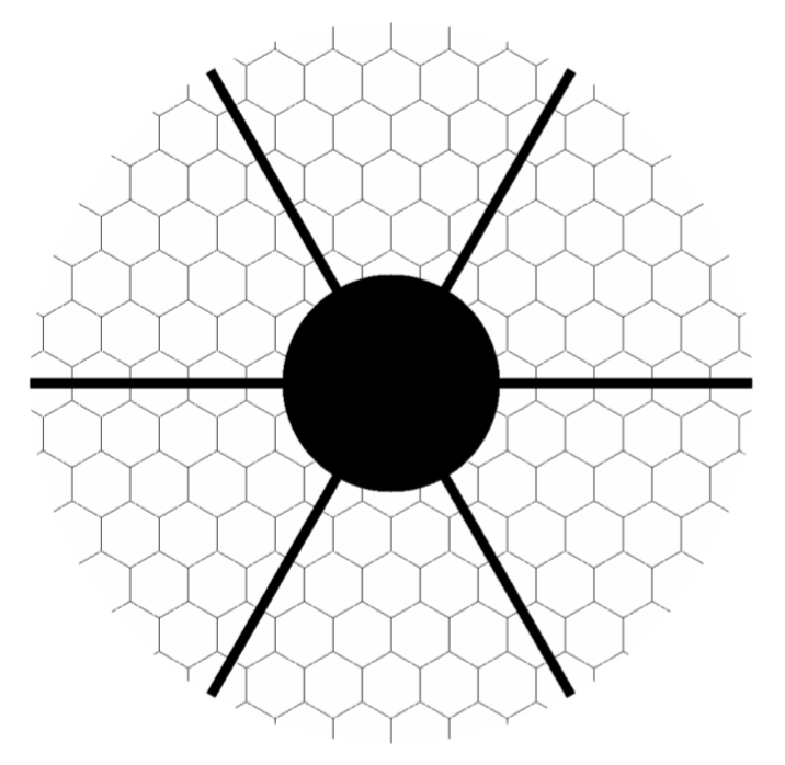 Simulated pupil of the SPEED telescope simulator exhibiting 30% central obscuration, 6 spiders and 163 segments.
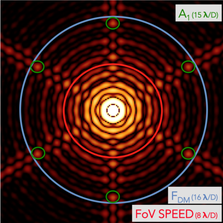
Simulated NiR PSF image. The Blue circle defines the wavefront shaping DMs cut-off frequency. The red circle defines the field of view (FoV) targetted by the project and is restricted to small angular separations. Green circles localized the first diffractive signatures from the primary mirror segmentation.
![]()